Direct memory access (DMA)
Table of Contents
Overview
Direct memory access (DMA) is a feature of modern computers that allows certain hardware subsystems within the computer to access system memory independently of the central processing unit (CPU).1
The three primary data transfer mechanisms for computer-based data acquisition are polling, interrupts (also known as programmed I/O), and direct memory access (DMA).2
DMA has several advantages over polling and interrupts.
- DMA is fast because a dedicated piece of hardware transfers data from one computer location to another and only one or two bus read/write cycles are required per piece of data transferred.
- DMA also minimizes latency in servicing a data acquisition device because the dedicated hardware responds more quickly than interrupts, and transfer time is short.
- DMA also off-loads the processor, which means the processor does not have to execute any instructions to transfer data.
A DMA controller manages several DMA channels, each of which can be programmed to perform a sequence of these DMA transfers. Devices, usually I/O peripherals, that acquire data that must be read (or devices that must output data and be written to) signal the DMA controller to perform a DMA transfer by asserting a hardware DMA request signal. A DMA request signal for each channel is routed to the DMA controller. This signal is monitored and responded to in much the same way that a processor handles interrupts. When the DMA controller sees a DMA request, the DMA controller responds by performing one or many data transfers from that I/O device into system memory or vice versa. Channels must be enabled by the processor for the DMA controller to respond to DMA requests. The number of transfers performed, transfer modes used, and memory locations accessed depends on how the DMA channel is programmed.
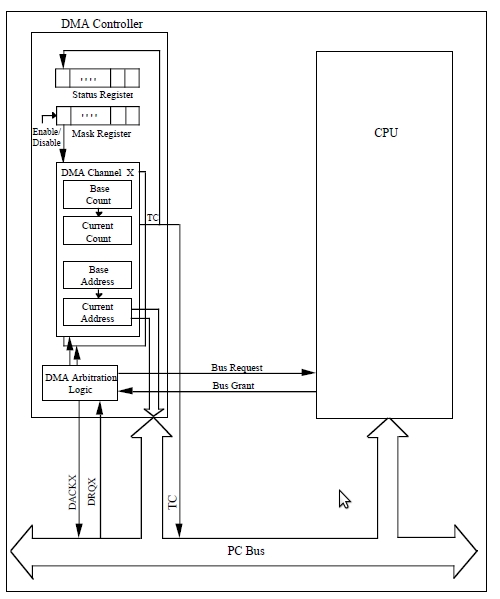
When the value in the current count register goes from 0 to -1, a terminal count (TC) signal is generated, which signifies the completion of the DMA transfer sequence. This termination event is referred to as reaching terminal count. DMA controllers often generate a hardware TC pulse during the last cycle of a DMA transfer sequence. This signal can be monitored by the I/O devices participating in the DMA transfers.
DMA controllers require reprogramming when a DMA channel reaches TC. Thus, DMA controllers require some CPU time, but far less than is required for the CPU to service device I/O interrupts. When a DMA channel reaches TC, the processor may need to reprogram the controller for additional DMA transfers. Some DMA controllers interrupt the processor whenever a channel terminates. DMA controllers also have mechanisms for automatically reprogramming a DMA channel when the DMA transfer sequence completes. These mechanisms include autoinitialization and buffer chaining.
Modes of operation
Burst mode
An entire block of data is transferred in one contiguous sequence.
Once the DMA controller is granted access to the system bus by the
CPU, it transfers all bytes of data in the data block before releasing
control of the system buses back to the CPU. The mode is also called
Block Transfer Mode.
Cycle stealing mode
In the cycle stealing mode, the DMA controller obtains access to the system bus the same way as in burst mode, using BR (Bus Request) and BG (Bus Grant) signals, which are the two signals controlling the interface between the CPU and the DMA controller. However, in cycle stealing mode, after one byte of data transfer, the control of the system bus is deasserted to the CPU via BG. It is then continually requested again via BR, transferring one byte of data per request, until the entire block of data has been transferred.
Transparent mode
The transparent mode takes the most time to transfer a block of data, yet it is also the most efficient mode in terms of overall system performance. The DMA controller only transfers data when the CPU is performing operations that do not use the system buses. It is the primary advantage of the transparent mode that the CPU never stops executing its programs and the DMA transfer is free in terms of time. The disadvantage of the transparent mode is that the hardware needs to determine when the CPU is not using the system buses, which can be complex and relatively expensive.
CPU and DMA addresses3
             CPU                  CPU                  Bus
           Virtual              Physical             Address
           Address              Address               Space
            Space                Space

          +-------+             +------+             +------+
          |       |             |MMIO  |   Offset    |      |
          |       |  Virtual    |Space |   applied   |      |
        C +-------+ --------> B +------+ ----------> +------+ A
          |       |  mapping    |      |   by host   |      |
+-----+   |       |             |      |   bridge    |      |   +--------+
|     |   |       |             +------+             |      |   |        |
| CPU |   |       |             | RAM  |             |      |   | Device |
|     |   |       |             |      |             |      |   |        |
+-----+   +-------+             +------+             +------+   +--------+
          |       |  Virtual    |Buffer|   Mapping   |      |
        X +-------+ --------> Y +------+ <---------- +------+ Z
          |       |  mapping    | RAM  |   by IOMMU
          |       |             |      |
          |       |             |      |
          +-------+             +------+
Cache Coherency4
On processors with a data cache an unwanted side effect of using DMA is the possibility that the contents of the cache are no longer coherent with respect to main memory which can lead to data corruption problems. As with any memory corruption problem, these are notoriously difficult to track down because the behaviour of the system may not be predictable.
The problem occurs when a DMA transfer changes the contents of main memory that has been cached by the processor. The data stored in the cache will be the previous value. However, when the cache is flushed the stale data will be written back to the main memory overwriting the new data stored by the DMA. The end result is that the data in main memory is not correct.
A similar problem can also occur with transfers from main memory. If a cached memory location is updated by the processor the new value in the cache will be different to the value in main memory until the cache is flushed. If a DMA transfer is initiated from main memory the stale data will be transferred instead of the data updated by the processor.
Some system hardware designs include a mechanism called bus snooping or cache snooping; the snooping hardware notices when an external DMA transfer refers to main memory using an address that matches data in the cache, and either flushes/invalidates the cache entry or “redirects” the transfer so that the DMA transfers the correct data and the state of the cache entry is updated accordingly. In systems with snooping, DMA drivers don’t have to worry about cache coherency.
The second solution is for the device driver software to explicitly flush or invalidate the data cache (depending on the transfer direction) before initiating a transfer or making data buffers available to bus mastering peripherals. This can also complicate the software and will cause more transfers between cache and main memory but it does allow the application to use any arbitrary region of cached memory as a data buffer.
Buffer Alignment
It is not unusual to find that DMA hardware needs data buffers or control structures to be located in memory at specific address boundaries (multiples of 8, 16, 32, etc). This simplifies the hardware design particularly when data is transferred in burst mode.
If the device driver is responsible for allocating the data buffers this is not normally a problem as there are standard routines, such as memalign(), that return memory aligned to a given address boundary. If the application is providing the buffer it may not be correctly aligned for the device. Other than forcing the application to using strictly aligned buffers, there are two possible solutions to this sort of problem, with different levels of complexity.
The simplest solution is to copy the data from the misaligned user buffer into a temporary buffer that is accessed during the DMA operation. However, depending on the size of the data buffer and the frequency of the data transfer this solution could add significant extra processing effort and reduce any performance gains from using DMA in the first place.
Another solution is to transfer the misaligned part of the buffer using programmed I/O. The remaining data in the buffer will then be correctly aligned for the hardware and can be transferred using DMA. The hardware may also require the DMA transfer count (buffer size) to be an integer multiple of the burst size. If this is the case the software must also transfer any remainder using programmed I/O.
The simple solution to this problem is to ensure that buffers used for DMA are multiples of the cache line size (typically 32 or 64 bytes) and are aligned to a cache-line size boundary.
Debugging problems with DMA
Dedicated DMA controllers and other DMA capable devices will usually provide status registers and error interrupts that can inform software if an error occurs. The status registers may give the transfer count, source address and destination address when the error occurred. There may also be bus-specific protocol registers that might show if the DMA transfer terminated because of a bus error, for example due to a misaligned access.
Bus analysers are also very useful tools for tracking down DMA errors. They can show what is happening on the address and data bus between the processor and the peripheral. They can also be set up to trigger and capture transactions that occur outside expected address windows on the bus, which helps to limit the amount of data captured and needing analysis.
PCI初始话DMA实例
以上是硬件实现DMA和DMA硬件传输模式的一些细节,仅做了解和参考。这里以 PCI为例,看设备如何初始化DMA,为之后操作做准备。
- 在platform devices列表中加入pci device的定义:
static u64 pci_ep_dmamask = ~(u32)0;
static struct platform_device ath_pci_ep_device = {
        .name                           = "ath-pciep",
        .id                             = 0,
        .dev = {
                .dma_mask               = &pci_ep_dmamask,
                .coherent_dma_mask      = 0xffffffff,
        },
        .num_resources                  = ARRAY_SIZE(ath_pci_ep_resources),
        .resource                       = ath_pci_ep_resources,
};
static struct resource ath_pci_ep_resources[] = {
        [0] = {
                .start  = ATH_PCI_EP_BASE_OFF,
                .end    = ATH_PCI_EP_BASE_OFF + 0xdff - 1,
                .flags  = IORESOURCE_MEM,
        },
        [1] = {
                .start  = ATH_CPU_IRQ_PCI_EP,
                .end    = ATH_CPU_IRQ_PCI_EP,
                .flags  = IORESOURCE_IRQ,
        },
};
- 之后
platform_add_devices调用platform_device_register会注册 pci设备。 - 在需要使用pci的driver中定义pci driver:
static struct pci_driver ath_pci_driver = {
    .name       = "ath_pci",
    .id_table   = ath_pci_id_table,
    .probe      = ath_pci_probe,
    .remove     = ath_pci_remove,
#ifdef ATH_BUS_PM
    .suspend    = ath_pci_suspend,
    .resume     = ath_pci_resume,
#endif /* ATH_BUS_PM */
    /* Linux 2.4.6 has save_state and enable_wake that are not used here */
};
pci_register_driver(&ath_pci_driver)注册相应driver。- 在
ath_pci_probe中pci_set_dma_mask(pdev, 0xffffffff)设置DMA mask,并作完pci driver的初始化工作。 - 之后看实际怎么使用DMA来使CPU与设备间互传。
DMA使用与实例
DMA memory要求
- 在物理地址上是连续的memory。
- 可以使用由
kmalloc(最大到128KB)或__get_free_pages(最大到 8MB)分配的memory。 - 可以使用支持DMA的block I/O和networking buffers(如struct skbbuf)。
- 不能使用
vmalloc的memory。
2种DMA mappings3
Consistent DMA mappings
Consistent DMA mappings which are usually mapped at driver initialization, unmapped at the end。
Think of "consistent" as "synchronous" or "coherent".
IMPORTANT: Consistent DMA memory does not preclude the usage of proper memory barriers. The CPU may reorder stores to consistent memory just as it may normal memory.
Example: if it is important for the device to see the first word of a descriptor updated before the second, you must do something like:
desc->word0 = address;
wmb();
desc->word1 = DESC_VALID;
in order to get correct behavior on all platforms.
Summarize as follows:
- DMA buffer allocated by the kernel
- Set up for the whole module life
- Can be expensive. Not recommended.
- Let both the CPU and device access the buffer at the same time.
using consistent DMA mappings.
dma_addr_t dma_handle;
cpu_addr = dma_alloc_coherent(dev, size, &dma_handle, gfp);
dma_free_coherent(dev, size, cpu_addr, dma_handle);
Streaming DMA mappings
Streaming DMA mappings which are usually mapped for one DMA
transfer, unmapped right after it (unless you use dma_sync_* below)
and for which hardware can optimize for sequential accesses.
This of "streaming" as "asynchronous" or "outside the coherency domain".
Summarize as follows:
- DMA buffer allocated by the driver.
- Set up for each transfer.
- Cheaper. Saves DMA registers.
- Only the device can access the buffer when the mapping is active.
Using streaming DMA mappings
/* To map a single region, you do: */
struct device *dev = &my_dev->dev;
dma_addr_t dma_handle;
void *addr = buffer->ptr;
size_t size = buffer->len;

dma_handle = dma_map_single(dev, addr, size, direction);
if (dma_mapping_error(dma_handle)) {
  /*
   * reduce current DMA mapping usage,
   * delay and try again later or
   * reset driver.
   */
  goto map_error_handling;
}
/* and to unmap it: */
dma_unmap_single(dev, dma_handle, size, direction);
PCI使用Streaming DMA mapping与WIFI芯片使用互传实例
- PCI driver初始化时,设置dma mask,
pci_set_dma_mask(pdev, 0xffffffff) - 发送到Device数据:
adf_nbuf_map_single(pdev->osdev, netbuf_copy, ADF_OS_DMA_TO_DEVICE);
//==》
dma_map_single(osdev->dev, buf->data,
               skb_end_pointer(buf) - buf->data, dir);
- 发送完umap并free skb:
adf_nbuf_unmap_single(
    vap->iv_ic->ic_adf_dev, (adf_nbuf_t) skb, ADF_OS_DMA_TO_DEVICE);
//===》
dma_unmap_single(osdev->dev, NBUF_MAPPED_PADDR_LO(buf),
                 skb_end_pointer(buf) - buf->data, dir);
adf_nbuf_free(skb);
- 从Device接收数据并umap:
ret = adf_nbuf_map_single(scn->adf_dev, nbuf, ADF_OS_DMA_FROM_DEVICE);
adf_nbuf_unmap_single(scn->adf_dev, (adf_nbuf_t)transfer_context, ADF_OS_DMA_FROM_DEVICE);
More examples:
DMA API Reference5
    #include <linux/dma-mapping.h>
    /* Using large DMA-coherent buffers */
    void *
    dma_alloc_coherent(struct device *dev, size_t size,
                                       dma_addr_t *dma_handle, gfp_t flag);
    /* It returns a pointer to the allocated region (in the processor's virtual
       address space) or NULL if the allocation failed. */
    void *
    dma_zalloc_coherent(struct device *dev, size_t size,
                        dma_addr_t *dma_handle, gfp_t flag);
    void
    dma_free_coherent(struct device *dev, size_t size, void *cpu_addr,
                      dma_addr_t dma_handle);

    /* Using small DMA-coherent buffers */
    #include <linux/dmapool.h>
    struct dma_pool *
    dma_pool_create(const char *name, struct device *dev,
                    size_t size, size_t align, size_t alloc);
    void *dma_pool_alloc(struct dma_pool *pool, gfp_t gfp_flags,
                         dma_addr_t *dma_handle);
    void dma_pool_free(struct dma_pool *pool, void *vaddr,
                       dma_addr_t addr);
    void dma_pool_destroy(struct dma_pool *pool);
    /* DMA addressing limitations */
    int
    dma_supported(struct device *dev, u64 mask);
    int
    dma_set_mask_and_coherent(struct device *dev, u64 mask);
    int
    dma_set_mask(struct device *dev, u64 mask);
    int
    dma_set_coherent_mask(struct device *dev, u64 mask);
    u64
    dma_get_required_mask(struct device *dev);
    /* Streaming DMA mappings */
    dma_addr_t
    dma_map_single(struct device *dev, void *cpu_addr, size_t size,
                   enum dma_data_direction direction);
    void
    dma_unmap_single(struct device *dev, dma_addr_t dma_addr, size_t size,
                     enum dma_data_direction direction);
    dma_addr_t
    dma_map_page(struct device *dev, struct page *page,
                 unsigned long offset, size_t size,
                 enum dma_data_direction direction);
    void
    dma_unmap_page(struct device *dev, dma_addr_t dma_address, size_t size,
                   enum dma_data_direction direction);
    int
    dma_mapping_error(struct device *dev, dma_addr_t dma_addr);
int
        dma_map_sg(struct device *dev, struct scatterlist *sg,
                int nents, enum dma_data_direction direction);
void
        dma_unmap_sg(struct device *dev, struct scatterlist *sg,
                int nhwentries, enum dma_data_direction direction);
void
dma_sync_single_for_cpu(struct device *dev, dma_addr_t dma_handle, size_t size,
                        enum dma_data_direction direction);
void
dma_sync_single_for_device(struct device *dev, dma_addr_t dma_handle, size_t size,
                           enum dma_data_direction direction);
void
dma_sync_sg_for_cpu(struct device *dev, struct scatterlist *sg, int nelems,
                    enum dma_data_direction direction);
void
dma_sync_sg_for_device(struct device *dev, struct scatterlist *sg, int nelems,
                       enum dma_data_direction direction);